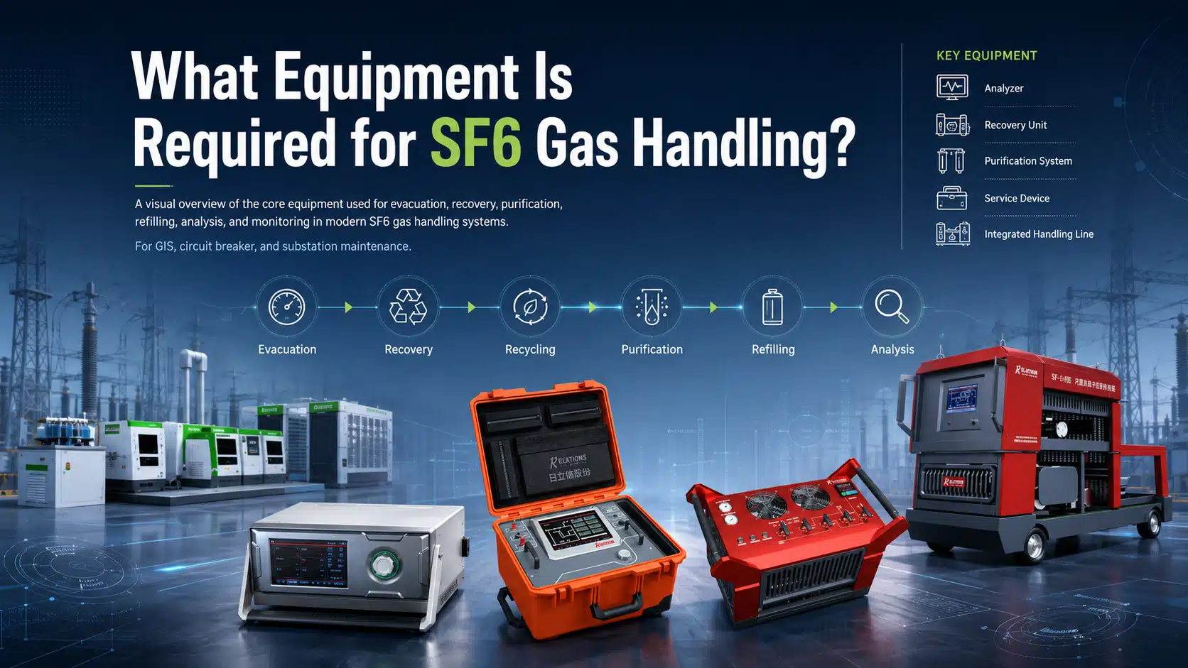
For utility, GIS, and switchgear maintenance teams, SF6 gas handling requires more than a recovery compressor. A complete process uses different equipment as the work moves from system preparation to gas recovery, treatment, refilling, and final verification. More importantly, each stage operates under different pressure conditions and serves a different technical purpose.
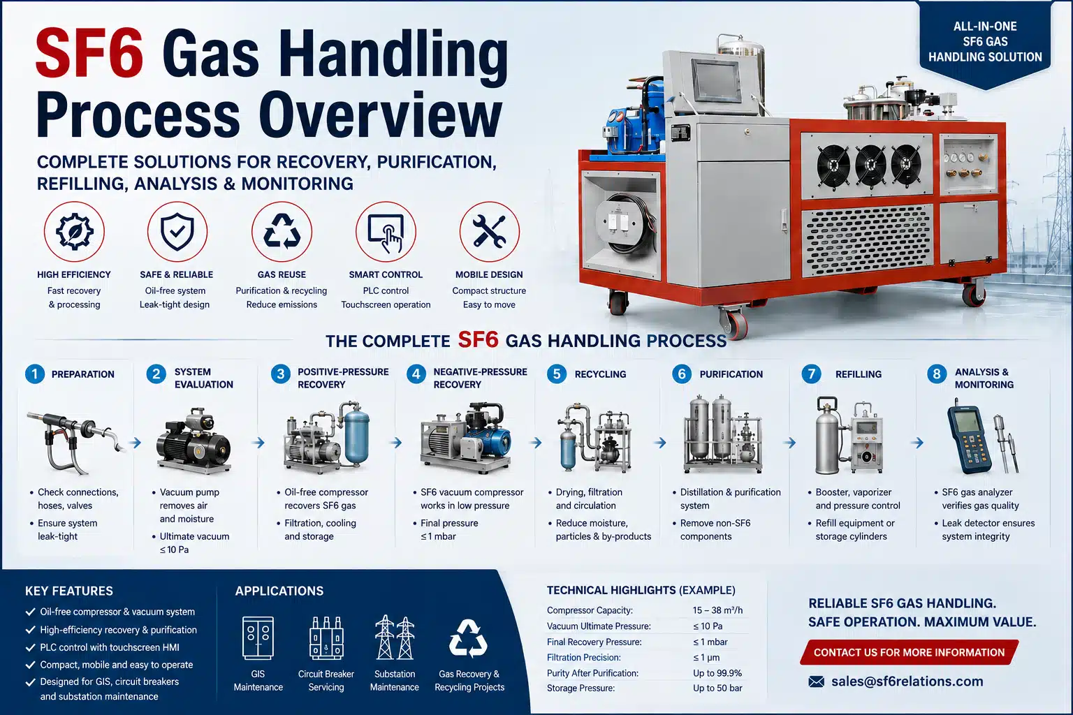
The complete SF6 gas handling process follows a controlled sequence:
Preparation → System Evacuation → Positive-Pressure Recovery → Negative-Pressure Recovery → Recycling → Purification → Refilling → Analysis & Monitoring
No single machine performs all of these functions under the same operating conditions. Instead, effective SF6 gas handling equipment combines vacuum equipment, compressors, filtration, purification, storage, filling, and gas-quality verification into one coordinated process.
1. Prepare the SF6 Gas Handling System
Reliable SF6 gas handling starts with a clean, leak-tight, and correctly connected gas path. Therefore, technicians first inspect the recovery hoses, self-sealing couplings, valves, pressure gauges, and control system before moving any gas.
At this stage, technicians connect the recovery lines, secure each coupling, verify valve positions, and confirm that the electrical and control systems operate normally. In addition, the work area requires appropriate ventilation when site conditions call for it.
These checks do not recover or treat SF6. Instead, they establish the operating conditions that allow the SF6 gas handling equipment to work as intended.
A sound connection strategy also reduces another common problem: air ingress. If ambient air enters the recovery circuit, it can affect gas quality and create additional work during later treatment. For this reason, connection integrity matters from the beginning of the process.
2. Evacuate the Recovery System Before SF6 Transfer
Before SF6 enters the recovery unit, technicians evacuate the recovery equipment, hoses, connecting lines, and relevant storage connections.
A vacuum pump performs this task. It removes air and residual moisture from the gas path before SF6 recovery begins.
For example, representative RF-series vacuum equipment includes:
- RF-S17: 17 m³/h, ultimate vacuum ≤10 Pa
- RF-S64: 64 m³/h, ultimate vacuum ≤10 Pa
Larger applications can use higher-capacity vacuum pumps or Roots-pump configurations when gas volume and evacuation time require more pumping capacity.
After the system reaches the required vacuum, technicians can hold the vacuum and monitor pressure rise. As a result, this step helps confirm both system cleanliness and connection integrity before gas transfer starts.
This distinction is important. The vacuum pump prepares the recovery equipment and connecting gas path. It does not perform the same function as the SF6 vacuum compressor used later for negative-pressure SF6 recovery. Industry equipment specifications make the same distinction between vacuum pumps for air evacuation and vacuum compressors or suction pumps for gas recovery.
3. Recover SF6 Under Positive Pressure
Once the gas path is ready, the SF6 recovery equipment removes gas from the electrical equipment.
During the first recovery stage, the gas compartment remains above atmospheric pressure. Therefore, the oil-free compressor provides most of the recovery capacity.
A typical gas path is:
Gas compartment → filtration → main compressor → cooling → storage
The main equipment usually includes an oil-free compressor, molecular-sieve or drying filters, a precision particle filter, a cooling system, a storage vessel, and a weighing system.
Representative compressor capacities from the supplied RF-series data include:
| Model | Main Compressor Capacity | Maximum Discharge Pressure |
|---|---|---|
| RF-151 | 15 m³/h | 50 bar |
| RF-391 | 30 m³/h | 50 bar |
| RF-300N | 38 m³/h | 50 bar |
During recovery, filtration already begins to improve gas condition. The treatment path reduces moisture, particles, and selected decomposition products before the recovered SF6 enters storage.
Meanwhile, compression increases gas temperature. The cooling system removes that heat and supports more efficient high-density or liquid storage where the equipment configuration allows it.
Therefore, the main compressor establishes the basic capacity for positive-pressure SF6 recovery. However, its rated flow does not describe the entire recovery process.
4. Continue SF6 Recovery Below Atmospheric Pressure
As gas-compartment pressure falls, the operating conditions change.
Near atmospheric pressure, the main compressor no longer receives the same favorable inlet conditions. Consequently, a dedicated SF6 vacuum compressor becomes increasingly important.
During negative-pressure recovery, the gas path typically follows:
Gas compartment → SF6 vacuum compressor → main compressor → cooling → storage
The vacuum compressor manages the low-pressure inlet side. At the same time, the main compressor maintains the discharge conditions required to move the recovered SF6 into storage.
Representative configurations include:
| Vacuum Compressor | Capacity | Final Pressure |
|---|---|---|
| RF-FS15 | 15 m³/h | ≤50 mbar |
| RF-FS20 | 20 m³/h | ≤0.5 mbar |
| RF-FS40 | 40 m³/h | ≤0.5 mbar |
Depending on the complete recovery-unit configuration and operating conditions, the system can reduce residual SF6 to approximately 1 mbar or below.
This stage also explains why a vacuum pump cannot replace an SF6 vacuum compressor.
The vacuum pump primarily evacuates air. By contrast, the vacuum compressor handles low-pressure SF6 and works with the main compressor to transfer that gas into storage.
Therefore, engineers should evaluate the main compressor and vacuum compressor as two parts of the same SF6 recovery equipment configuration rather than as interchangeable components.
5. Recycle Recovered SF6
Recovery does not automatically make used SF6 suitable for reuse.
Depending on operating history and maintenance conditions, recovered gas may contain moisture, solid particles, decomposition products, or other contaminants. Therefore, the next stage uses circulation, drying, filtration, and adsorption to improve gas condition.
Typical recycling equipment includes:
- molecular-sieve dryer
- precision particle filter
- circulation loop
- treatment or purification tank
- cooling system
In the supplied RF-series configurations, particle filtration can reach ≤1 μm.
During recycling, the system circulates recovered SF6 through the treatment path several times when necessary. As a result, molecular sieves reduce moisture, particle filters remove solids, and adsorption media capture selected decomposition products.
However, filtration has limits.
It can improve moisture and contamination levels, but it does not necessarily remove non-SF6 gases that reduce purity. Industry guidance similarly distinguishes normal filtration from reconditioning: filtration handles moisture and contaminants, while deeper separation addresses other vapors or gaseous components.
Therefore, recycling serves as an important intermediate step, but gas analysis must determine whether further treatment is necessary.
6. Purify SF6 When Recycling Is Not Enough
When repeated recycling cannot achieve the required gas condition, the process moves to deeper SF6 purification or reconditioning.
This stage uses more specialized SF6 gas handling equipment, including distillation columns, purification tanks, refrigeration systems, heating systems, pretreatment equipment, and tail-gas treatment units.
The RF-300N provides one example of this type of configuration. According to the supplied equipment data, it combines:
- a 38 m³/h oil-free compressor
- a twin-column distillation system
- a 300 L purification tank
- a 50 bar tank design pressure
Recovered gas may contain non-SF6 components such as air, CF4, C2F6, or C3F8. Therefore, deeper treatment must do more than pass the gas through another filter.
Instead, the purification system controls temperature and pressure to separate SF6 from unwanted gas components according to differences in their physical properties. Industry separation systems likewise use SF6 condensation under pressure and low-temperature conditions to separate the target gas from other components.
Meanwhile, refrigeration supports condensation, and the purification tank provides controlled storage during the treatment process. Depending on the configuration, separated gases then move through an appropriate tail-gas treatment route.
Nevertheless, SF6 purity alone does not determine whether treated gas is ready for reuse.
Technicians also need to evaluate moisture, decomposition products, and other applicable gas-quality parameters.
Therefore, purification and verification must work together.
7. Refill Electrical Equipment or Storage Cylinders
After the gas reaches the required condition, the SF6 gas handling process moves from treatment to controlled transfer.
Refilling equipment manages pressure, gas phase, and transferred quantity as qualified SF6 returns to electrical equipment or storage.
Typical equipment includes:
- oil-free booster
- vaporizer
- pressure regulator
- tank heating system
- weighing system
- filling hose
- self-sealing couplings
According to the supplied equipment data, a typical liquid-SF6 booster provides 5 m³/h capacity, while the vaporizer uses 1.5 kW of heating power. The pressure-control system can provide an adjustable output range of 1–10 bar.
Direct Filling
Direct filling uses the available pressure difference between the storage system and the receiving gas compartment.
Therefore, it works without additional pressure boosting when storage and equipment pressures provide sufficient differential pressure.
Pressure-Assisted Filling
When direct pressure difference is not sufficient, the booster increases the discharge pressure and maintains controlled gas transfer.
This method can support refilling of electrical equipment as storage pressure changes.
Liquid SF6 Filling
The system can also transfer SF6 in liquid form into suitable storage cylinders.
In this case, technicians need an accurate weighing system. Because liquefied SF6 can remain at similar vapor pressure across very different fill quantities, cylinder pressure alone does not provide a reliable indication of stored mass. Therefore, gas-handling practice uses weighing to control cylinder filling.
When SF6 must return to the gas phase for equipment filling, the vaporizer and heating system support controlled vaporization and gas transfer.
8. Verify Gas Quality and System Integrity
The SF6 gas handling process does not end when the gas reaches equipment or storage.
Instead, technicians verify the final gas condition and check the integrity of the gas system.
SF6 Gas Analysis
An SF6 gas analyzer can measure key gas-quality parameters such as:
- SF6 purity
- moisture or dew point
- SO2
- H2S
- CO
- H2
These measurements provide a technical basis for assessing the condition of recovered or treated SF6.
Therefore, gas analysis connects the treatment process with the final decision on further use.
SF6 Leak Detection
Next, technicians use an SF6 leak detector to check likely leakage points, including:
- valves
- flanges
- hoses
- self-sealing couplings
- GIS sealing points
For example, the supplied LM-068 infrared leak detector provides a sensitivity of 0.1 × 10⁻⁶ and a response time of 1 second.
Portable leak detection supports field inspection after recovery, maintenance, and refilling. In addition, it helps technicians locate small leaks before they develop into larger gas-loss problems.
Monitoring and Emission Control
For installations that require continuous oversight, fixed monitoring systems can track SF6-related conditions over time.
Meanwhile, deeper purification processes also require controlled management of separated gases. Tail-gas treatment and controlled handling therefore form part of the broader emission-control strategy.
Thus, recovery and treatment manage the SF6 itself, while analysis, leak detection, and monitoring verify the result.
How the Complete SF6 Gas Handling Process Works
| Stage | Main Operation | Key Equipment | Main Purpose |
|---|---|---|---|
| 1. Preparation | Inspect and connect the handling system | Hoses, couplings, valves, gauges | Establish a clean, leak-tight gas path |
| 2. System Evacuation | Evacuate recovery equipment and connecting lines | Vacuum pump, vacuum gauge | Remove air and moisture before recovery |
| 3. Positive-Pressure Recovery | Recover most SF6 above atmospheric pressure | Oil-free compressor, filters, cooling system, storage | Transfer and store recovered SF6 |
| 4. Negative-Pressure Recovery | Continue recovery below atmospheric pressure | SF6 vacuum compressor, main compressor | Reduce residual SF6 to the required final recovery pressure |
| 5. Recycling | Dry, filter, and circulate recovered gas | Molecular sieve, particle filter, circulation system | Reduce manageable contaminants |
| 6. Purification | Apply deeper gas treatment | Distillation system, purification tank, refrigeration system | Separate SF6 from unwanted gas components |
| 7. Refilling | Return qualified SF6 to equipment or storage | Booster, vaporizer, regulator, weighing system | Control pressure and transferred quantity |
| 8. Analysis & Monitoring | Verify gas quality and system condition | SF6 gas analyzer, leak detector, monitoring system | Confirm gas condition and system integrity |
In practical terms, the complete sequence is:
Prepare → Evacuate → Positive-Pressure Recovery → Negative-Pressure Recovery → Recycle → Purify → Refill → Verify
Each stage solves a different technical problem. Therefore, an effective SF6 gas handling system depends on how these functions work together rather than on one machine or one rated flow value.
Each Stage Requires the Right SF6 Gas Equipment
Complete SF6 gas handling depends on matching equipment to the condition of the gas and the purpose of each operation.
Vacuum equipment prepares the gas path. Oil-free compressors handle positive-pressure recovery, while SF6 vacuum compressors extend recovery into the low-pressure range. Filtration and purification equipment then improve gas condition. After treatment, refilling equipment controls the return of qualified SF6, while analysis and monitoring verify the final result.
For this reason, no single SF6 recovery unit defines the entire process.
The appropriate configuration depends on gas quantity, recovery pressure, gas condition, treatment requirements, storage capacity, and the intended application.
Those operating parameters also provide the best basis for technical discussion. If you are evaluating SF6 gas handling equipment for a specific GIS maintenance, purification, or reuse project, you can share the gas volume, pressure range, treatment target, and storage conditions with our technical team at [email protected].
This allows both sides to compare process configurations on the same engineering basis rather than relying on a single equipment rating.