Why SF6 System Evacuation Is Required Before Gas Recovery?
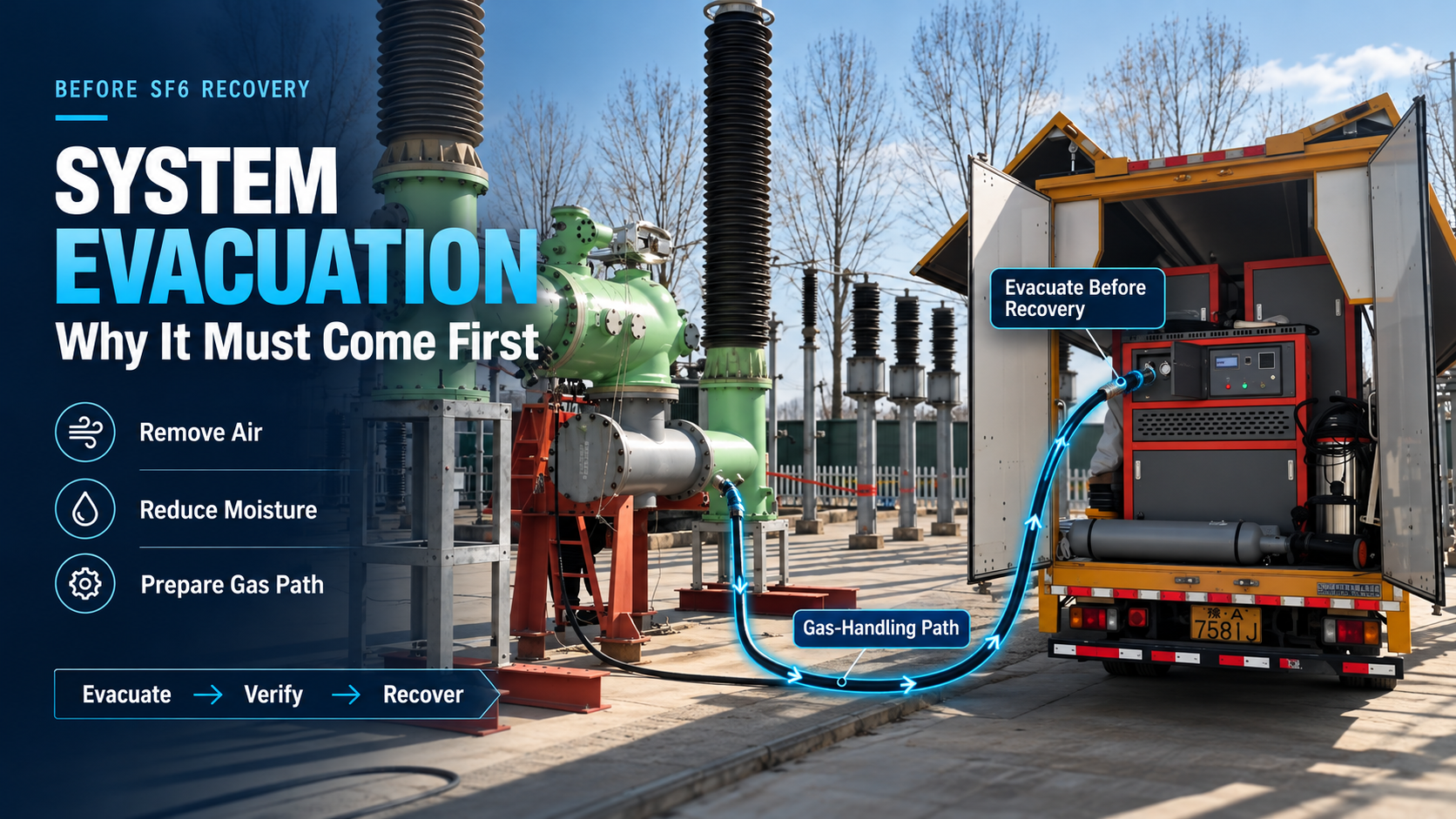
Connecting SF6 recovery equipment to a gas compartment does not make the recovery path ready. Recovery hoses, couplings, valves, manifolds, and the internal gas path of the recovery unit contain ambient air. They may also hold residual moisture from earlier use or storage. If recovery starts immediately, that air and moisture can enter the recovered gas.
SF6 system evacuation removes this condition before recovery begins. In this article, the term refers to evacuating the gas-handling path, including recovery hoses, pipelines, connectors, valves, manifolds, and the internal gas path of the recovery unit. It does not refer to evacuating an SF6-filled GIS or switchgear gas compartment. The operating sequence is straightforward: remove air and residual moisture, establish a controlled gas path, verify the vacuum condition, and then begin SF6 gas recovery.
What Is SF6 System Evacuation?
SF6 system evacuation pulls a vacuum on the connected gas-handling path before any SF6 leaves the gas compartment. The evacuated path includes every connected volume that recovered gas will pass through. These components are exposed to ambient air when disconnected. A stored hose contains air, while a manifold opened during an earlier job may also contain moisture. Even a leak-tight recovery unit still contains ambient air in its internal piping until the gas path is evacuated.
System evacuation and SF6 recovery are separate operations. Evacuation prepares the gas path; recovery transfers SF6 from the equipment to a storage vessel. Distinguishing the two steps is important because the gas compartment must remain isolated from the vacuum pump during pre-recovery evacuation.
| Aspect | System Evacuation | SF6 Recovery |
|---|---|---|
| Process | Pulls a vacuum on the gas-handling path | Transfers SF6 out of the gas compartment |
| What is removed | Ambient air and residual moisture | SF6 gas from the equipment |
| Main purpose | Prepare the gas path for transfer | Remove SF6 before maintenance or servicing |
| When it happens | Before recovery begins | After the gas path is evacuated and verified |
| Gas compartment state | Isolated from the vacuum pump | Opened to the recovery system |
| Typical flow direction | Gas-handling path to vacuum pump | Compartment to storage tank or cylinder |
Why Evacuation Is Required Before SF6 Recovery
Evacuation addresses two main sources of contamination in the recovery path: ambient air and residual moisture. Both can affect the condition of the recovered gas and make later gas-quality results harder to interpret.
Remove Air from the Gas Path
Air remaining in hoses, pipelines, manifolds, and internal piping mixes with SF6 when recovery begins. The recovered gas then contains an air fraction introduced by the handling equipment rather than by the original gas compartment. This changes the measured composition and creates uncertainty during later analysis.
The effect is especially important when gas-quality records are compared over time. If air enters during recovery, a later purity result may reflect both the original condition of the SF6 and contamination introduced by the handling path. Evacuating the path first removes this avoidable variable.
Reduce Residual Moisture
Ambient air contains water vapor, and components exposed to humid conditions can retain moisture on internal surfaces. Hoses left open during storage, disconnected manifolds, and internal piping can all contribute to the moisture load. Evacuation helps reduce residual moisture and water vapor before SF6 enters the gas path.
Evacuation does not remove all moisture. Components exposed to liquid water, heavy condensation, or prolonged humid conditions may require separate drying or inspection. The purpose of pre-recovery evacuation is to reduce avoidable contamination introduced by the handling process, not to change the condition of the SF6 already inside the compartment.
Together, removing air and reducing residual moisture creates a more controlled path for gas transfer. This helps keep contamination from hoses, connectors, valves, manifolds, and recovery-unit piping out of the recovered gas.
Equipment Used for System Evacuation
The vacuum pump is the main component, but evacuation performance depends on the complete gas path. High pumping speed cannot compensate for a leaking coupling, a restricted hose, an incorrectly positioned valve, or a path that has not been properly isolated. The vacuum reached at the connected system therefore matters more than the pump specification alone.
| Equipment | Function | What to Check |
|---|---|---|
| Vacuum pump | Creates the low-pressure condition in the gas path | Operating condition and anti-backflow protection if fitted |
| Vacuum gauge | Indicates the vacuum level in the evacuated path | Calibration status and connection point |
| Recovery hoses | Connect the recovery unit to the equipment | Cleanliness, dryness, damage, sealing surfaces |
| Valves | Control evacuation and recovery flow paths | Correct open or closed position |
| Couplings and connectors | Join hoses and equipment | Seat condition, locking, self-sealing function |
| Manifolds | Distribute flow between multiple lines or ports | Valve position and unused ports closed |
| Integrated recovery equipment | Combines evacuation and recovery functions | Available evacuation function and correct port configuration |
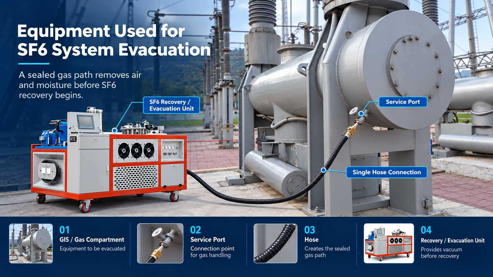
Some SF6 recovery units include an integrated vacuum pump or a dedicated evacuation connection. Depending on the equipment design, the internal gas path and connected hoses can be evacuated together before recovery begins. Other systems use a separate vacuum pump and gauge. In either case, the objective remains the same: prepare the complete gas path before the SF6 compartment is opened to the recovery system.
Key Parameters in SF6 System Evacuation
Vacuum level is the main parameter used to judge evacuation, but it should not be considered alone. Pumping speed, system volume, hose geometry, leakage, and vacuum stability all affect actual evacuation performance. No single vacuum value applies to every recovery system; the target must follow the equipment procedure, manufacturer requirement, or project specification.
| Parameter | What It Means | Why It Matters |
|---|---|---|
| Vacuum level | Pressure remaining in the evacuated gas path | Indicates the degree of evacuation reached |
| Pumping speed | Volume the vacuum pump can move per unit of time | Influences how quickly the target vacuum can be reached |
| Internal gas-path volume | Total volume of hoses, piping, manifolds, and unit internals | Larger volumes generally require more evacuation time |
| Hose diameter and length | Internal cross-section and total hose length | Long or narrow hoses increase flow resistance |
| Vacuum stability | Pressure behavior after the pump is isolated | Helps identify significant leakage or gas release |
Higher pumping speed can shorten evacuation time when other system conditions remain unchanged, but the relationship is not strictly linear. Long hoses, small internal diameters, leakage, system volume, and gas release from internal surfaces can all limit performance. A short and direct gas path usually evacuates more efficiently than a long path with narrow hoses.
Vacuum stability provides another useful check. After the required vacuum is reached, some procedures specify an observation or holding period. A significant pressure rise may indicate leakage, trapped gas, or gas release from internal surfaces. This check should not be confused with a final pressure leak test, which is a separate verification with its own method and acceptance criteria.
What Happens Without System Evacuation?
Skipping evacuation introduces avoidable uncertainty into the recovery process. Air remaining in hoses and piping can mix with the recovered SF6, while residual moisture can enter the gas stream. The recovered gas may then contain contamination introduced during handling rather than contamination that was originally present in the gas compartment.
This also makes later gas analysis harder to interpret. If purity or moisture results change after recovery, operators may have difficulty determining whether the condition came from the original SF6 or from the recovery process itself. Maintenance records and trend comparisons can therefore become less reliable. System evacuation reduces this uncertainty before gas transfer begins.
Basic Evacuation Procedure Before Recovery
The exact operating sequence depends on the recovery equipment and site procedure, but the basic logic remains consistent: connect the recovery system, keep the SF6 compartment isolated, evacuate the gas-handling path, verify the vacuum condition, and then reconfigure the system for recovery.
| Step | Action | Key Check |
|---|---|---|
| 1 | Connect the recovery equipment | Connections secured and gas-tight |
| 2 | Keep the SF6 gas compartment isolated | Compartment valve closed |
| 3 | Open the evacuation path | Valves aligned for evacuation only |
| 4 | Start the vacuum pump | Pump operating normally |
| 5 | Check vacuum level and stability | Required vacuum condition reached and verified |
| 6 | Reconfigure the valves for recovery | Flow path set for SF6 recovery |
During evacuation, the SF6 gas compartment must not be connected directly to the vacuum pump. The vacuum pump acts on the gas-handling path alone. The compartment remains isolated until the required vacuum condition has been reached and the connected path has been checked.
If the procedure specifies a holding period, the vacuum pump is isolated or stopped as required and the pressure is observed. Once the vacuum condition is acceptable, the valve configuration can be changed from evacuation to recovery. Only then should the SF6 compartment be opened to the recovery system.
When Is the System Ready for Recovery?
The system is ready for recovery when three basic conditions are met:
- The required vacuum level has been reached.
- Pressure remains acceptably stable during the specified check.
- All connections and valves are correctly configured for recovery.
Only after these conditions are confirmed should the SF6 gas compartment be opened to the recovery system. Opening it earlier allows SF6 to enter a gas path that may still contain air or moisture, defeating the purpose of evacuation.
Why SF6 System Evacuation Matters
SF6 recovery should begin only after the gas-handling path has been evacuated and verified. This preparation reduces avoidable air and moisture entry and gives operators a controlled starting point for gas transfer. It also supports more reliable gas-quality evaluation because the recovery process introduces fewer variables into the recovered gas.
The equipment used for evacuation should match the required workflow, gas-path volume, hose configuration, and target vacuum condition. An integrated recovery unit can simplify the process, while a separate vacuum pump and gauge can perform the same preparation when the system is configured correctly.
For SF6 recovery and evacuation equipment selection, contact [email protected].
Frequently Asked Questions
What is the difference between system evacuation and SF6 recovery?
System evacuation removes air and reduces residual moisture in the gas-handling path before gas transfer begins. SF6 recovery transfers SF6 from the gas compartment to a storage tank or cylinder.
Why should recovery hoses be evacuated before SF6 recovery?
Recovery hoses contain ambient air when they are disconnected and may also contain residual moisture. Evacuating them helps reduce contamination introduced during gas transfer.
How much vacuum is required before SF6 recovery?
The required vacuum level depends on the recovery equipment, manufacturer procedure, and project specification. No single value applies to every system.
Can an integrated SF6 recovery unit perform system evacuation?
Many integrated recovery units include a vacuum pump or dedicated evacuation function. The available functions and operating sequence depend on the specific equipment design.