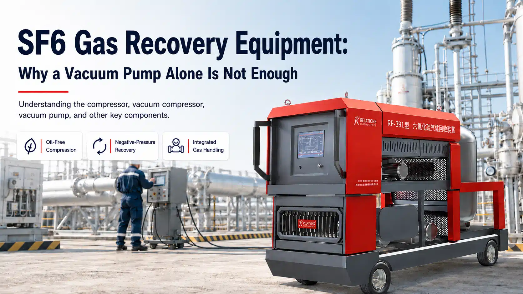
A typical SF6 service job may look simple at first. A technician connects SF6 gas recovery equipment to a GIS compartment, starts the system, and watches the pressure fall. However, the process changes as soon as SF6 begins to leave the compartment.At first, the gas is relatively dense and easy to transfer. As pressure falls, the recovery rate changes. Once the compartment approaches atmospheric pressure, the remaining SF6 becomes harder to remove. Meanwhile, the recovered gas still needs filtration, compression, cooling, and storage.
That is why SF6 gas recovery equipment needs more than a vacuum pump. The oil-free compressor handles most of the initial transfer. Next, the SF6 vacuum compressor supports low-pressure recovery. By contrast, the SF6 vacuum pump mainly removes air before refilling.Taken together,these components form a complete SF6 gas recovery system. More importantly, understanding their roles explains why one large pump does not always mean faster recovery.
SF6 Gas Recovery Equipment: Recovery vs. Vacuum Evacuation
Before looking inside an SF6 recovery unit, it helps to separate two operations that are often confused.
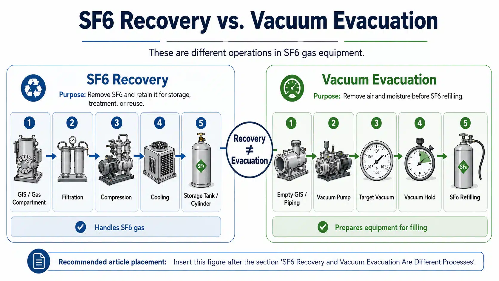
During recovery, the equipment removes SF6 from GIS, circuit breakers, or other gas-insulated equipment. However, the gas remains inside a closed handling system.Instead, it follows a controlled path:Gas compartment → filtration → compression → cooling → storage.Afterward, the recovered gas can be tested, treated, transferred, or reused as required.
By contrast,vacuum evacuation serves a different purpose. After maintenance, air and residual moisture may remain inside the compartment. Therefore, an SF6 vacuum pump evacuates the compartment before SF6 returns.The sequence is different:Empty compartment → vacuum pump → target vacuum → vacuum hold → SF6 filling.
In other words, recovery removes and retains SF6, while evacuation removes air before filling. For this reason, this distinction is fundamental to modern SF6 gas recovery equipment.
Why an SF6 Vacuum Pump Alone Cannot Handle SF6 Gas Recovery
In practice, an SF6 vacuum pump can lower pressure inside a gas compartment. However, effective recovery also requires compression, gas cleaning, transfer, and storage.
Recovered SF6 Must Be Compressed and Stored
First, recovered SF6 needs a destination. Therefore, the system must transfer it into a storage tank or cylinder instead of releasing it.As a result, two pressure conditions develop. GIS pressure keeps falling, while the storage vessel may already be pressurized. As a result, the system needs a compressor that can move gas against the storage pressure.Even so, a standard vacuum pump cannot complete this transfer alone. For this reason, the oil-free SF6 compressor becomes the main recovery machine.
SF6 Recovery Pressure Changes as Gas Leaves the GIS
At first, positive-pressure SF6 moves toward the recovery unit relatively easily. As recovery continues, gas density decreases.Consequently, the compressor receives less gas mass for the same inlet volume. Eventually, pressure approaches atmospheric level and positive-pressure recovery becomes less effective.Therefore, the system must continue below atmospheric pressure. Consequently, the SF6 vacuum compressor becomes important.
SF6 Gas Recovery Equipment Must Protect Gas Quality
At the same time, gas quality matters. For example, SF6 may carry moisture, fine particles, or decomposition products. Therefore, effective equipment usually includes filtration and drying stages.In addition, the gas path should avoid new contamination. For this reason, RF-series recovery systems use an oil-free main compressor.
The Complete SF6 Gas Path Affects Recovery Speed
More importantly,pump capacity is only one part of performance. In practice, SF6 must also pass through hoses, filters, valves, fittings, and couplings.For example, a high-capacity compressor connected through a narrow hose may never reach its full potential. Moreover, restrictions become more important as recovery pressure falls.Therefore, rated pump capacity does not equal actual SF6 recovery rate. Instead, engineers need to evaluate the complete gas path.
Oil-Free SF6 Compressor: The Main SF6 Recovery Stage
The oil-free SF6 compressor performs most positive-pressure recovery. At first, it draws SF6 from the electrical equipment. Then it raises gas pressure and sends the gas toward storage.In addition,because the compressor sits directly in the gas path, its design also affects gas quality. By contrast with an oil-lubricated gas path, an oil-free compressor avoids adding compressor oil to recovered SF6. This matters when the gas may later return to service.
Typical RF-Series SF6 Compressor Specifications
| Model | Main Compressor Capacity | Maximum Discharge Pressure |
|---|---|---|
| RF-051 | 15 m³/h | 50 bar |
| RF-151 | 15 m³/h | 50 bar |
| RF-391 | 30 m³/h | 50 bar |
| RF-300J | 38 m³/h | Configuration dependent |
These figures describe rated capacity. However, recovery flow does not stay constant.For example, the RF-391 main compressor is rated at 30 m³/h. Early in the cycle, it receives relatively dense SF6. Later, inlet pressure falls while storage pressure may rise.Therefore, actual recovery time depends on both inlet and outlet conditions. In other words, compressor flow alone cannot define SF6 gas recovery equipment performance.
SF6 Vacuum Compressor: The Key to Negative-Pressure SF6 Recovery
Once GIS pressure approaches atmospheric pressure, recovery becomes more difficult. The main compressor still provides discharge compression. However, its inlet conditions are less favorable.As a result, the SF6 vacuum compressor continues drawing gas from the compartment. In many integrated systems, it works in series with the main compressor:GIS → SF6 vacuum compressor → main compressor → cooling → storage.In practice, the vacuum compressor handles the low-pressure inlet side. Meanwhile, the main compressor handles the higher-pressure discharge side. As a result, recovery can continue below atmospheric pressure.
Typical RF-Series SF6 Vacuum Compressor Performance
| Model | Vacuum Compressor Capacity | Final SF6 Recovery Pressure |
|---|---|---|
| RF-051 | 7.2 m³/h | ≤1 mbar |
| RF-391 | 15 m³/h | ≤1 mbar |
| RF-300J | 30 m³/h | <1 mbar |
For example, the RF-391 combines a 30 m³/h main compressor with a 15 m³/h vacuum compressor. Together, they support recovery after the positive-pressure stage.For example, under specified operating conditions, final recovery pressure can reach ≤1 mbar. More specifically, this value shows how deeply the system can remove residual SF6.
Final SF6 Recovery Pressure vs. SF6 Vacuum Pump Ultimate Vacuum
These terms describe different functions. Final recovery pressure refers to residual pressure after SF6 recovery.By contrast, ultimate vacuum describes the evacuation capability of the SF6 vacuum pump. Therefore, 1 mbar recovery pressure and 10 Pa ultimate vacuum do not represent the same operation.Therefore,this distinction matters when comparing SF6 gas recovery equipment.
SF6 Vacuum Pump: Preparing the GIS for SF6 Refilling
After recovery and maintenance, the operating goal changes. At this stage, the technician must remove air and residual moisture from the empty GIS compartment and piping.In practice, this is the main role of the SF6 vacuum pump. Once the required vacuum is reached, the operator can perform a vacuum hold check. After that, SF6 filling can begin.
RF-Series SF6 Vacuum Pump Specifications
| Model | Vacuum Pumping Speed | Ultimate Vacuum |
|---|---|---|
| RF-051 | 17 m³/h | ≤10 Pa |
| RF-151 | 64 m³/h | ≤0.1 mbar |
| RF-391 | 64 m³/h | ≤10 Pa |
| RF-300J | 64 m³/h | <10 Pa |
These figures can cause confusion. For example, the RF-391 includes:
- 64 m³/h SF6 vacuum pump
- 30 m³/h main SF6 compressor
- 15 m³/h SF6 vacuum compressor
At first glance, 64 m³/h may look like the recovery rate. However, it describes nominal air-evacuation capacity.Meanwhile, the 30 m³/h compressor handles main recovery, and the 15 m³/h vacuum compressor supports the low-pressure stage.In other words, the three ratings describe different functions.
SF6 Recovery Filters Protect the Gas and SF6 Gas Recovery Equipment
At this stage, filtration becomes important because the recovered SF6 may carry contaminants. For example, the gas may carry moisture, dust, or solid particles. Therefore, RF recovery systems use different filters for different contaminants.
SF6 Drying Filter in the Gas Recovery System
The drying stage helps remove moisture from the gas stream. RF equipment can use molecular-sieve media, and some configurations allow regeneration.In addition, adsorption can help reduce selected acidic contaminants. However, moisture removal and particle filtration are different functions.
SF6 Particle Filter in the Recovery Unit
The particle filter removes dust and solid contamination. Relevant RF-series equipment provides a filtration rating of:≤1 μm.As a result, valves, compressors, and regulators receive better protection. At the same time, less solid contamination reaches storage.
Cooling Improves SF6 Gas Recovery and Storage Efficiency
Compression raises SF6 temperature. Therefore, larger recovery systems often use dedicated cooling.Under suitable pressure and temperature conditions, cooling supports SF6 condensation. As a result, the gas can be stored at higher density and use tank volume more efficiently.Typical RF configurations include:
- RF-051: mechanical refrigeration or water cooling
- RF-391: 3 HP refrigeration system
- RF-300J: 5 HP refrigeration system
Importantly, the compressor does not liquefy SF6 by itself. Instead, compression raises pressure while refrigeration removes heat. Together, they support high-density or liquid storage.
SF6 Storage Tanks Receive Gas From the Recovery Equipment
Once SF6 leaves the GIS, it needs secure storage. RF-series recovery units use different tank sizes for different gas volumes.
| Model | Integrated Storage Capacity |
|---|---|
| RF-051 | 70 L |
| RF-151 | 600 L |
| RF-391 | 300 L |
| RFG-1001 | 1,600 L |
The RF-151 tank, for example, has a design pressure of 50 bar. However, tank volume alone does not define usable SF6 capacity.In practice, temperature, storage pressure, liquid fill level, and vessel limits also matter. Therefore, engineers should compare storage volume together with operating conditions.
Digital Weighing Tracks SF6 Recovery and Filling Quantity
Pressure shows system condition, but it does not directly show transferred SF6 mass. For example, temperature can change pressure without changing gas mass.For that reason, weighing provides a clearer inventory value. A typical RF digital weighing system offers:
- Range: 0–120 kg
- Accuracy: ±20 g
- tare function
- preset weight control
- automatic shutoff
During recovery, the scale records gas entering storage. Later, it can measure the amount returned during filling. As a result, the same system supports inventory control and overfill protection.
SF6 Recovery Hoses and Couplings Can Limit Actual Flow
A smaller component can limit even a large compressor. For example, the hose may become the main restriction.Typical RF configurations include:
- DN13 × 10 m recovery hose
- DN13 × 3 m filling hose
- DN20 × 10 m hose on larger equipment
- DN20 and DN40 self-sealing SF6 couplings
A long hose increases flow resistance. Likewise, a smaller internal diameter creates more restriction.However, low-pressure recovery is especially sensitive to gas-path resistance. Therefore, connection size becomes more important near final recovery pressure.For example, a high-flow vacuum compressor connected through a restrictive DN13 path may not deliver the same field performance as a larger gas path. As a result, rated flow can differ from actual recovery flow.
Self-Sealing Couplings for SF6 Gas Recovery Equipment
Self-sealing couplings help control gas loss. When the operator disconnects the hose, the coupling closes automatically.Meanwhile, coupling diameter affects flow resistance. Therefore, larger DN20 or DN40 connections can benefit high-capacity systems.
Valves Direct SF6 Through the Recovery System
As the job moves from recovery to evacuation and filling, the gas path must change. Manual ball valves provide isolation and service access.Meanwhile, solenoid valve manifolds support automatic switching between:
- SF6 recovery
- negative-pressure SF6 recovery
- evacuation
- storage
- SF6 filling
Because one incorrect valve position can interrupt the process, automated control reduces repetitive manual steps and improves consistency.
Pressure and Vacuum Instruments Monitor SF6 Recovery Equipment
Operators need to see what the system is doing in real time. For this reason, RF equipment monitors several pressure zones.Typical ranges include:
- Inlet pressure: -1 to 10 bar
- Outlet pressure: 0 to 70 bar
- Vacuum range: 0.001 to 1,000 mbar
During positive-pressure recovery, inlet and discharge readings show compressor conditions. Later, vacuum readings become more important.As recovery pressure falls, the controller can use these measurements to switch stages. Therefore, pressure measurement helps coordinate the recovery sequence.
PLC Control Turns Components Into an Integrated SF6 Gas Recovery System
Pumps, tanks, and valves only become an integrated system when their operation is coordinated. Therefore, PLC control plays an important role.Depending on the RF configuration, the system can include a Siemens S7-200 PLC and a 10- to 15-inch touchscreen. The controller can manage:
- SF6 compressor operation
- valve sequencing
- negative-pressure SF6 recovery
- refrigeration
- pressure limits
- alarms
- automatic shutdown
- operating status
As conditions change, the PLC keeps each component in the correct stage. For example, it can end one recovery step and prepare the next gas path.As a result, the technician does not need to make every change manually. In addition, safety valves provide a separate mechanical safeguard against excessive pressure.
How SF6 Gas Recovery Equipment Works Through a Complete Service Cycle
The individual components make more sense when we follow a real SF6 gas recovery sequence.
Step 1: Connect the SF6 Gas Recovery Equipment
First, the technician connects the GIS compartment to the recovery unit. Next, the team checks hoses, storage capacity, valve positions, and initial pressure.In addition, system tightness should be confirmed before recovery starts. At this point, every later stage depends on a secure gas path.
Step 2: Start Positive-Pressure SF6 Gas Recovery
Once the system is ready, the oil-free compressor begins transferring gas. From there, SF6 passes through the required filters and enters compression.Next, cooling removes heat before the gas enters storage. At this stage, recovery is usually faster because the compartment remains under positive pressure.However, conditions change as SF6 leaves the GIS.
Step 3: Switch to Negative-Pressure SF6 Recovery
Eventually, compartment pressure approaches atmospheric pressure. At this point, the SF6 vacuum compressor becomes more important.It continues pulling residual SF6 from the GIS. Meanwhile, the main compressor maintains the discharge pressure needed for storage.As a result, selected RF recovery units can continue to 1 mbar or below under specified conditions. Therefore, deep recovery depends on cooperation between the two compressors.
Step 4: Confirm the Final SF6 Recovery Pressure
Once the target pressure is reached, the system stops recovery. However, the job should not always end the instant the display reaches that value.At this point, the operator may isolate the compartment and monitor pressure stability. For example, pressure may rise slightly as gas leaves dead spaces or temperature equalizes.Therefore, stabilization provides useful information before the next stage.
Step 5: Perform Maintenance and Evacuate the GIS
After recovery, maintenance can proceed. Once the compartment is closed again, the SF6 vacuum pump begins a different job.Then, it removes air and residual moisture. Next, the system reaches the specified vacuum and performs the required vacuum hold.Only after this stage should SF6 return to the equipment.
Step 6: Refill the GIS With SF6
Finally, stored SF6 moves back toward the electrical equipment. If the gas is stored as a liquid, the vaporizer and heating system help return it to the gas phase.Next, the pressure regulator controls filling pressure. At the same time, the weighing system tracks transferred SF6.Once the required filling condition is reached, the process can stop. In this way, one recovery unit supports recovery, evacuation, storage, and refilling as connected gas-handling operations.
SF6 Vaporizer and Pressure Regulator Support Refilling
Refilling also requires controlled gas conditions. A vaporizer converts liquid SF6 into gas before it enters the electrical equipment.Typical RF vaporizer power is:1.5 kW.In colder environments, an auxiliary tank heater can increase vapor production. Next, the pressure regulator controls outlet pressure.A typical RF adjustment range is:1–10 bar.Together, these components provide a stable gas supply during the final filling stage.
When SF6 Gas Recovery Equipment Needs Deeper Gas Treatment
For clean or lightly contaminated gas, basic recovery and filtration may be sufficient. However, fault gas or heavily contaminated SF6 can require additional treatment.Therefore, larger systems such as RF-300N or RF-300J can add pretreatment and distillation functions. Depending on the process, treatment can include:
- drying
- adsorption
- contaminant pretreatment
- washing and neutralization
- distillation
- controlled liquid filling
Under defined operating conditions, purified SF6 can reach:Purity ≥99.9%.Even so, purity should not be the only reuse criterion. Therefore, operators should also verify moisture and relevant decomposition products before returning treated SF6 to service.
Which Parameters Define SF6 Gas Recovery Equipment Performance?
By now, one point should be clear: no single number describes an SF6 recovery unit. Instead, several parameters work together.
| Parameter | What It Tells the Engineer |
|---|---|
| Main SF6 compressor capacity | Main SF6 transfer capability |
| Maximum discharge pressure | Ability to transfer SF6 into pressurized storage |
| SF6 vacuum compressor capacity | Low-pressure SF6 recovery capability |
| Final SF6 recovery pressure | Depth of residual SF6 recovery |
| SF6 vacuum pump speed | Air evacuation capability |
| Ultimate vacuum | Deep evacuation performance |
| Storage capacity | Available onboard SF6 storage |
| Cooling capacity | Heat removal and liquid-storage support |
| Hose diameter | SF6 gas-path flow restriction |
| Coupling size | Connection flow capability |
| Filter performance | SF6 and equipment protection |
| Weighing accuracy | SF6 mass measurement |
| PLC logic | Coordination of the complete SF6 recovery process |
For example, the RF-391 vacuum pump is rated at 64 m³/h. However, its main compressor is rated at 30 m³/h, while the vacuum compressor is rated at 15 m³/h.In other words, each value describes a different function. Therefore, calling the RF-391 a “64 m³/h SF6 recovery unit” would be misleading.Actual recovery time still depends on:
- GIS compartment volume
- initial pressure
- required final SF6 recovery pressure
- gas temperature
- storage pressure
- hose diameter
- coupling size
- cooling conditions
That is why engineers need to compare complete system performance.
What to Check Before Choosing SF6 Gas Recovery Equipment
When engineers compare SF6 gas recovery equipment, vacuum-pump size should not be the only question. Instead, start with the recovery requirement.How much SF6 is inside the compartment? What final recovery pressure is required? How quickly must the job be completed?Next, examine the equipment. Key questions include:
- Does the system use an oil-free SF6 compressor?
- What is the main SF6 compressor capacity?
- What discharge pressure can the compressor reach?
- Does the unit include a dedicated SF6 vacuum compressor?
- How low can the system reduce SF6 pressure during recovery?
- Is the SF6 vacuum pump intended mainly for air evacuation?
- Which SF6 recovery hose and coupling sizes are supplied?
- What drying and filtration stages are included?
- How does the equipment cool recovered SF6?
- What onboard SF6 storage capacity is available?
- Which SF6 gas handling stages are automated?
- What pressure protection does the SF6 recovery system provide?
Together, these questions provide a more realistic view of SF6 gas recovery equipment performance.
Efficient SF6 Gas Recovery Equipment Depends on the Complete System
An SF6 service job may begin with a simple goal: remove SF6 from a GIS compartment. However, pressure soon changes, storage fills, and the remaining gas becomes harder to recover.That is why one SF6 vacuum pump cannot handle the complete process. The oil-free compressor manages the main transfer stage. Next, the SF6 vacuum compressor continues recovery below atmospheric pressure.By contrast, the SF6 vacuum pump removes air before refilling. Meanwhile, filters protect gas quality, while cooling and storage systems manage recovered SF6. Hoses and couplings also influence actual flow.Finally, valves, instruments, weighing systems, and PLC controls keep each stage working together.
For that reason, engineers should evaluate SF6 gas recovery equipment as an integrated system, not as a collection of pump ratings.Ultimately, the best configuration depends on gas volume, final recovery pressure, storage capacity, connection size, and target recovery time. Every site presents different conditions, so practical experience matters as much as equipment data. If you would like to discuss a recovery problem, compare operating approaches, or simply exchange field experience, you can reach us anytime at [email protected].