RF-A Modular SF6 Recovery Unit for On-Site Gas Handling
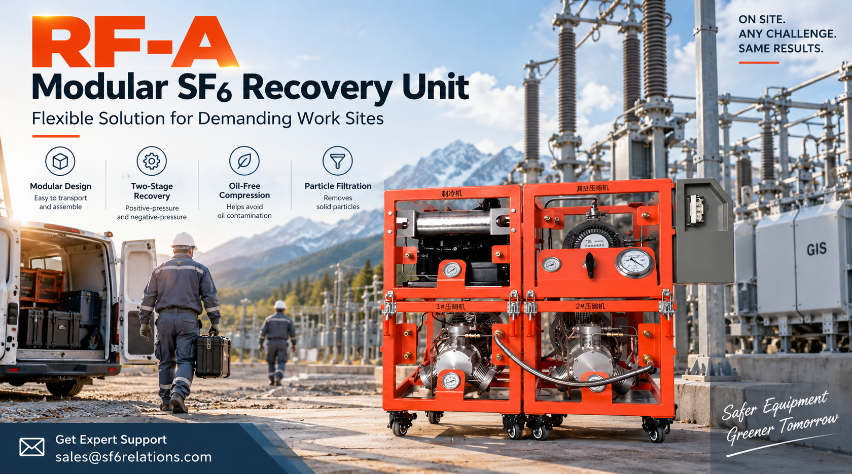
Moving an SF6 recovery unit is usually straightforward when the equipment can reach the work area directly. Remote substations, indoor installations, and restricted access routes make the job more difficult.
The RF-A modular SF6 recovery unit addresses these conditions with a modular structure. Technicians can separate the RF-A for transport, move each module to the work area, and assemble the complete system on site. After assembly, the RF-A performs both positive-pressure SF6 recovery and negative-pressure SF6 recovery.
The concept is simple: bring the recovery unit to the electrical equipment instead of trying to move one large integrated SF6 recovery unit through every access point.
What Is the RF-A Modular SF6 Recovery Unit?
The RF-A is a modular SF6 recovery unit for servicing SF6-filled electrical equipment.
Its modular structure separates the main recovery functions into individual sections. Technicians can transport these sections separately and assemble them at the work area.
The RF-A follows DL/T 662 for design and manufacturing. Its modular structure allows operators to separate individual sections for transport and combine them into one complete SF6 recovery unit when needed.
This structure gives the RF-A a clear advantage when transportation and site access create part of the maintenance challenge.
How the RF-A Is Built and Assembled
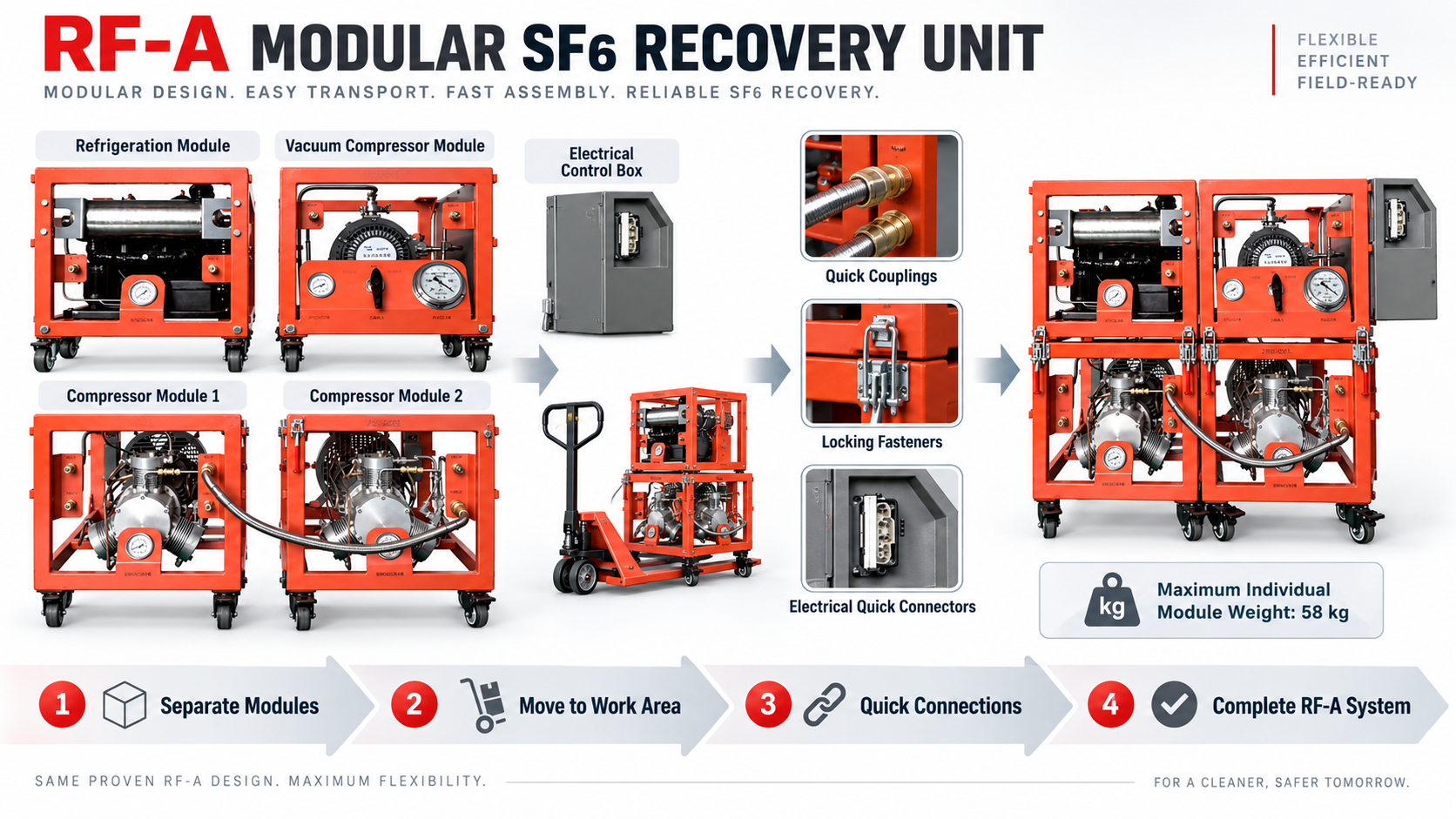
The RF-A divides its main recovery functions among several modules. Once technicians complete the assembly, these modules work together as one system.
Main System Modules
The RF-A includes:
- Compressor Module 1
- Compressor Module 2
- Refrigeration Module
- Vacuum Compressor Module
- Electrical Control Box
The two main recovery compressors perform positive-pressure SF6 recovery. The vacuum compressor performs negative-pressure SF6 recovery. The refrigeration module supports the recovery process, while the electrical control box connects and controls the operating modules.
This arrangement lets technicians transport the RF-A in smaller sections without changing the function of the complete system after assembly.
How to Assemble the RF-A on Site
Technicians assemble the RF-A with locking fasteners, labeled piping connections, quick couplings, and electrical quick connectors.
They match the labeled piping connections to the corresponding module interfaces and connect the electrical control box to each module through electrical quick connectors. Locking fasteners secure the modules together. Normal assembly does not require special tools.
After assembly, technicians perform system evacuation before starting SF6 recovery.
The basic sequence is:
Transport the Modules → Assemble the RF-A → Connect Piping and Power → Perform System Evacuation → Start SF6 Recovery
Why the RF-A Is Easier to Transport and Use On Site
The modular structure provides the most value when technicians cannot easily move an integrated SF6 recovery unit to the work area.
Easier Transport to Remote and Difficult Work Sites
Remote substations may have poor road conditions, limited lifting equipment, or difficult access.
Technicians can separate the RF-A before transport and move the individual modules independently. The heaviest individual module weighs 58 kg.
Instead of moving the complete RF-A system as one assembly, technicians can transport the modules separately and assemble them after reaching the work area.
This approach makes the RF-A practical for locations where site conditions make it difficult to move larger integrated SF6 recovery equipment.
Better Access in Indoor and Space-Constrained Areas
Indoor substations create a different problem. Doors, corridors, equipment rooms, and limited space around switchgear may restrict the movement of an integrated SF6 recovery unit.
Technicians can move the RF-A modules into the work area separately and assemble the complete system close to the electrical equipment.
The benefit is practical: technicians do not need to move one large recovery unit through every doorway or access route.
How the RF-A Performs Two-Stage SF6 Recovery
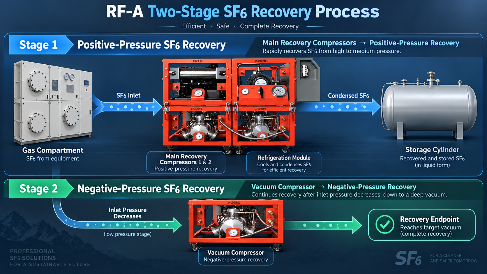
The RF-A uses a two-stage SF6 recovery process that combines positive-pressure SF6 recovery with negative-pressure SF6 recovery.
Different compressors handle each stage.
Positive-Pressure SF6 Recovery
During positive-pressure SF6 recovery, the RF-A operates Compressor Module 1, Compressor Module 2, and the refrigeration module.
The main recovery compressors remove SF6 from the gas compartment, compress the gas, and transfer it toward the storage cylinder. The refrigeration module also operates during this stage.
The basic flow is:
Gas Compartment → Main Recovery Compressors → Refrigeration Module → Storage Cylinder
The operating manual should provide the exact valve positions and operating sequence. For this article, the important point is how each component contributes to SF6 recovery.
Negative-Pressure SF6 Recovery with the Vacuum Compressor
As recovery continues, the inlet pressure decreases.
The RF-A then starts the vacuum compressor for negative-pressure SF6 recovery. The vacuum compressor continues the recovery process after the positive-pressure stage and operates until the system reaches the specified recovery endpoint.
The two compressor functions are clear:
Main recovery compressors → positive-pressure SF6 recovery
Vacuum compressor → negative-pressure SF6 recovery
This arrangement allows the RF-A to continue recovering SF6 as the inlet pressure drops.
How the Two Recovery Stages Work Together
The RF-A assigns different pressure conditions to different compressors.
The main recovery compressors handle positive-pressure SF6 recovery first. As the inlet pressure falls, the vacuum compressor takes over for negative-pressure SF6 recovery.
This two-stage process allows the RF-A to continue recovery without relying on one compressor across the entire recovery process.
How Oil-Free Compression Helps Control Oil Contamination
The RF-A uses oil-free compression to reduce the risk of introducing oil contamination during SF6 recovery.
SF6 flows through the compressors during recovery. Therefore, compressor design directly affects contamination control.
Oil-free compression helps reduce one potential source of additional oil contamination. However, it does not replace SF6 purification or gas analysis.
For more information about this topic, see:
Why Oil-Free Compressors Matter in SF6 Recovery
How Filtration and Refrigeration Support SF6 Recovery
The RF-A combines particle filtration and refrigeration with its two-stage SF6 recovery process. Each function supports a different part of the process.
Particle Filtration
Recovered SF6 may contain solid particles from electrical equipment or the SF6 gas circuit.
The RF-A uses particle filtration to remove solid particles during recovery.
Particle filtration and oil-free compression perform different functions:
Oil-free compression → reduces the risk of additional oil contamination
Particle filtration → removes solid particles from recovered SF6
Each function addresses a different contamination source.
Refrigeration-Assisted Recovery
The refrigeration module operates with the main recovery compressors during positive-pressure SF6 recovery.
The RF-A also uses refrigeration-assisted recovery to support operation under higher ambient-temperature conditions.
The refrigeration module supports the overall recovery process. It does not act as a separate recovery method.
Where the RF-A Modular SF6 Recovery Unit Is Used
The RF-A works well in applications where technicians must consider both SF6 recovery requirements and physical access to the work area.
Remote and Difficult-to-Access Substations
Remote locations may have poor road access or limited equipment-handling resources.
Technicians can transport the RF-A as separate modules instead of moving the complete system as one assembly. This modular approach makes transport easier when site conditions limit the use of an integrated SF6 recovery unit.
Indoor and Space-Constrained Installations
Indoor substations may have narrow doorways, restricted access routes, or limited working space.
Technicians can move the individual modules into the work area and assemble the complete RF-A system next to the electrical equipment.
This gives the RF-A a practical advantage when an integrated SF6 recovery unit cannot easily reach the work area.
Circuit Breaker and GIS Maintenance
The RF-A supports maintenance of gas-filled switchgear, circuit breakers, and SF6 gas-insulated switchgear (GIS).
For these tasks, the RF-A combines:
Positive-Pressure SF6 Recovery → Negative-Pressure SF6 Recovery → Refrigeration → Particle Filtration → Storage
The modular structure becomes especially useful when technicians need to work in locations that restrict access for larger equipment.
Training and Technical Education
Universities and technical training programs can also use the RF-A for demonstrations and operator training.
Its modular structure makes the main functional sections easy to identify. Trainees can see how the main recovery compressors, vacuum compressor, refrigeration module, and electrical control box work together during the recovery process.
Overall, the RF-A provides a practical option when transportation, access, lifting conditions, or indoor space make an integrated SF6 recovery unit difficult to use.
What to Check Before Operating the RF-A
Technicians should complete several checks before starting the RF-A.
They should verify:
- module locking points;
- piping connections;
- quick couplings;
- electrical connections;
- system evacuation;
- inlet pressure;
- inlet and outlet pressure readings;
- system tightness;
- shutdown sequence.
The RF-A has a maximum inlet working pressure of ≤0.3 MPag. The system also requires evacuation after assembly, and the specified annual equipment leakage rate is ≤1%.
Operators should follow the manufacturer’s operating procedure for exact valve positions, recovery endpoints, system evacuation requirements, and shutdown steps.
Key RF-A Technical Specifications
| Parameter | RF-A Specification |
|---|---|
| System Structure | Modular |
| Recovery Method | Positive- and negative-pressure two-stage SF6 recovery |
| Main Recovery Compressors | Dual-compressor configuration |
| Negative-Pressure SF6 Recovery | Vacuum compressor |
| Refrigeration | Refrigeration module |
| Maximum Individual Module Weight | 58 kg |
| Module Connection | Locking fasteners and quick connections |
| Maximum Inlet Working Pressure | ≤0.3 MPag |
| Annual Equipment Leakage Rate | ≤1% |
| Design and Manufacturing Standard | DL/T 662 |
The available product information also lists compressor rate, vacuum compressor rate, particle filtration precision, power supply, rated power, ambient temperature, relative humidity, and total equipment weight as technical parameters. However, the available document does not provide the corresponding numerical values, so they are not included here.
Modular SF6 Recovery for Practical Field Service
The RF-A combines modular construction with two-stage SF6 recovery.
Its field workflow is straightforward:
Separate for Transport → Move to the Work Area → Assemble On Site → Perform System Evacuation → Start SF6 Recovery
The modular structure makes transportation and site access easier. The main recovery compressors perform positive-pressure SF6 recovery, while the vacuum compressor performs negative-pressure SF6 recovery. Oil-free compression, particle filtration, and the refrigeration module support the overall recovery process.
This combination makes the RF-A suitable for remote substations, indoor installations, GIS maintenance, technical training, and other applications where technicians cannot easily move an integrated SF6 recovery unit directly to the work area.
For RF-A configuration and project selection, provide the SF6 quantity, electrical equipment type, site access conditions, and maintenance requirements. Our engineering team can use this information to recommend a configuration for the actual field application.
FAQ
What is a modular SF6 recovery unit?
A modular SF6 recovery unit separates its main functions into individual modules. Technicians can transport the modules separately and assemble the complete system at the work area.
How is the RF-A different from an integrated SF6 recovery unit?
The RF-A uses a modular structure. Technicians can transport its modules separately and assemble them on site. An integrated SF6 recovery unit remains as one complete assembly.
Can technicians transport the RF-A as separate modules?
Yes. Technicians can separate the RF-A for transport and assemble it on site. The heaviest individual module weighs 58 kg.
How does the RF-A perform negative-pressure SF6 recovery?
The RF-A uses a vacuum compressor for negative-pressure SF6 recovery. The vacuum compressor operates after the positive-pressure stage and continues recovery as the inlet pressure decreases.
Where can technicians use the RF-A modular SF6 recovery unit?
Technicians can use the RF-A at remote and indoor substations, gas-filled switchgear, circuit breakers, GIS maintenance sites, universities, and technical training facilities.