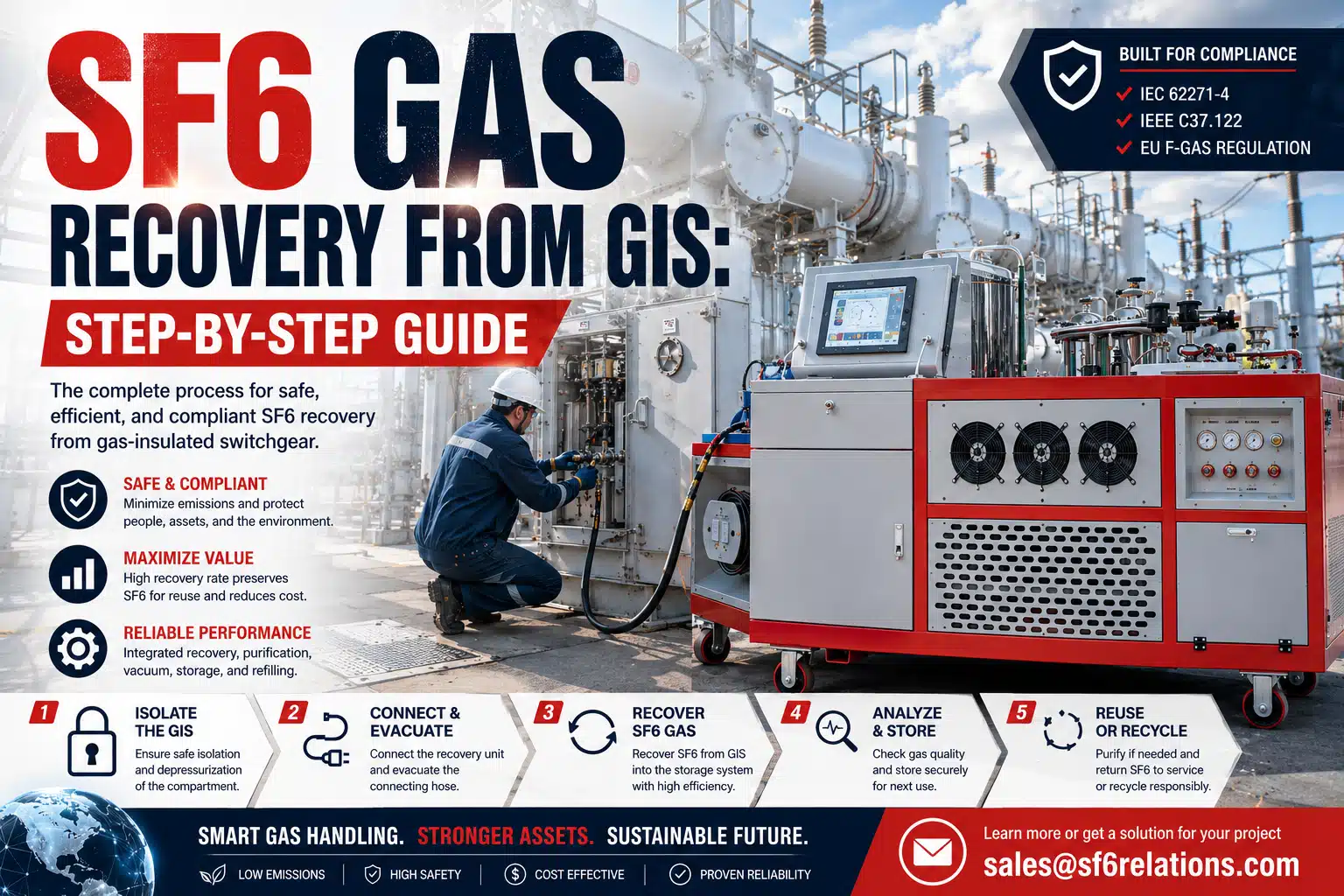
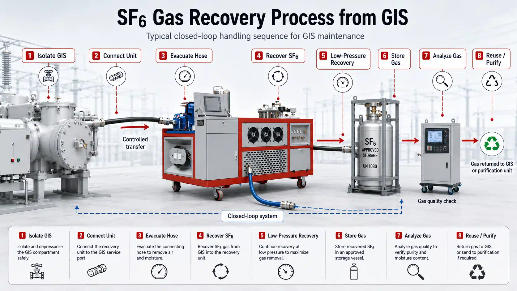
To recover SF6 gas from GIS equipment, technicians follow a controlled sequence: isolate the gas compartment, connect the SF6 gas recovery unit, evacuate the connecting hose, transfer the gas into controlled storage, continue recovery into the required low-pressure range, and then evaluate the recovered SF6 before reuse or further treatment.
Although the basic sequence remains consistent, GIS designs, gas quantities, operating pressures, and maintenance requirements vary from project to project. Therefore, technicians should always follow the GIS manufacturer’s instructions and the approved site procedure rather than apply one fixed recovery pressure or valve sequence to every installation.
Proper SF6 gas recovery does more than empty a GIS compartment. It also helps keep air and moisture out of the gas circuit, limits avoidable SF6 loss, preserves recovered gas for possible reuse, and provides a controlled starting point for inspection, repair, or decommissioning.
Why Recover SF6 Gas Before GIS Maintenance?
GIS equipment divides its insulating gas into defined gas compartments. Before technicians open one of these compartments for internal inspection, repair, component replacement, or decommissioning, they first remove the SF6 through a closed gas-handling system.
First, controlled SF6 gas recovery keeps the gas inside the handling and storage circuit instead of releasing it during maintenance. In addition, it allows the maintenance team to retain the recovered SF6 for subsequent gas-quality analysis.
However, recovery and reuse are not the same operation. Technicians should evaluate recovered SF6 before returning it to GIS equipment, especially when the gas comes from a compartment with an unknown service history, abnormal operating condition, or evidence of internal discharge.
Therefore, a professional GIS maintenance procedure normally treats recovery, storage, analysis, purification, and refilling as related but distinct stages.
What Equipment Is Needed to Recover SF6 from GIS?
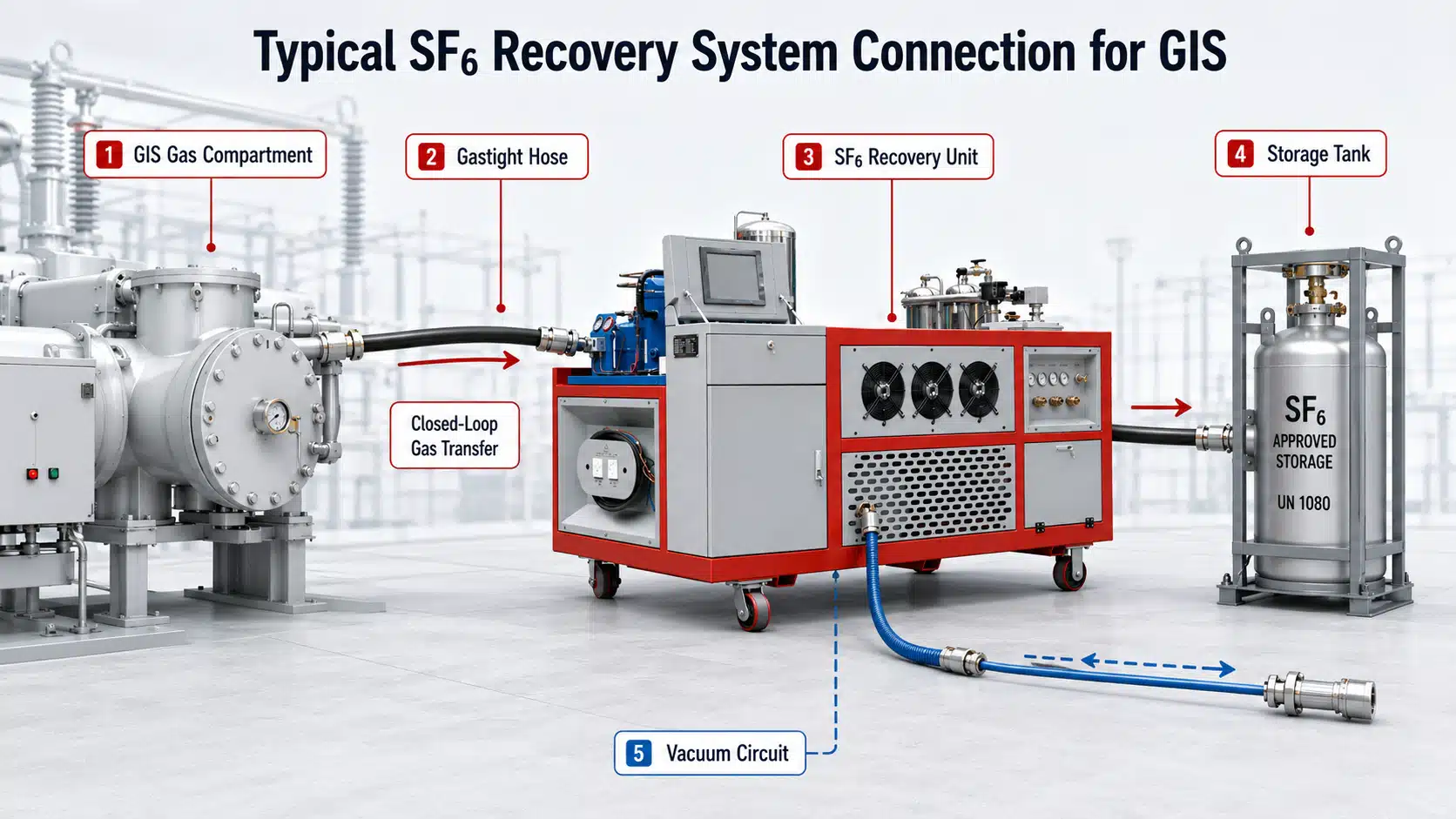
A typical GIS SF6 recovery setup includes:
- an SF6 gas recovery unit;
- gastight recovery hoses;
- compatible valves and couplings;
- an SF6 storage tank or approved gas cylinders;
- pressure-monitoring instruments;
- a vacuum system; and
- SF6 gas-analysis equipment when the recovered gas will be evaluated for reuse.
The SF6 gas recovery unit performs the primary gas-transfer operation. Depending on the equipment configuration, one integrated system may also support vacuum evacuation, purification, storage, recycling, and refilling.
For example, the RF-300J SF6 Gas Recovery and Purification Unit integrates recovery, purification, vacuum evacuation, recycling, storage, and refilling functions in one system.
It is also important to distinguish vacuum evacuation from SF6 recovery.
The vacuum pump primarily removes air and moisture from an empty compartment, pipeline, or connecting hose. By contrast, the recovery system transfers SF6 from the GIS into controlled storage.
Therefore, technicians should not interpret a vacuum pump’s ultimate-vacuum specification as the final SF6 recovery pressure of a GIS compartment. These values describe different functions within the overall gas-handling process.
What Should Be Checked Before SF6 Gas Recovery?
Before technicians recover SF6 gas from GIS equipment, they should confirm the gas compartment identification, expected gas quantity, operating pressure, service connection, available storage capacity, and required condition before compartment opening.
In addition, technicians should inspect hoses, valves, couplings, seals, and storage connections. A clean and leak-tight gas path reduces the possibility of introducing atmospheric air or moisture into the recovered SF6.
Next, verify that the storage tank or cylinders provide sufficient available capacity for the gas expected from the GIS compartment. Operators should also confirm that the storage system remains within its specified filling and pressure limits throughout the operation.
If the GIS has experienced an internal fault or abnormal discharge event, keep the recovered gas separate from known reusable SF6 until gas analysis confirms its condition. Consequently, an uncertain batch does not affect a larger quantity of stored gas.
How to Recover SF6 Gas from GIS Equipment: Step by Step
Step 1: Isolate the GIS Gas Compartment
Follow the approved electrical isolation, grounding, lockout, and maintenance procedure for the GIS.
Then identify the correct gas compartment and service connection. Because different GIS designs use different gas-zone arrangements and valve configurations, technicians should verify the equipment documentation before they begin gas handling.
Step 2: Connect the SF6 Gas Recovery Unit
Connect the recovery hose between the GIS service connection and the SF6 gas recovery unit.
Next, connect the recovery equipment to its internal storage vessel or the designated external gas cylinder, depending on the system configuration.
Before opening the gas path, check every coupling, valve, and hose connection. A secure gas circuit helps control SF6 during transfer and reduces the risk of gas loss during the recovery operation.
Step 3: Evacuate the Connecting Hose
Before allowing GIS gas into the connecting hose, evacuate the hose according to the recovery equipment operating procedure.
This step removes atmospheric air and moisture from the connection line. Therefore, the hose enters service as a prepared part of the gas circuit instead of introducing unnecessary contamination into the recovered SF6.
Importantly, hose evacuation prepares the gas path; it does not recover SF6 from the GIS.
Step 4: Start the Main SF6 Gas Recovery Stage
Open the required valves in the approved sequence and start the SF6 gas recovery unit.
The recovery system transfers SF6 from the GIS gas compartment into the designated storage system. During this stage, technicians monitor the GIS pressure, storage-side conditions, and recovery equipment operating status.
If the unit includes filtration or drying during recovery, the gas passes through the corresponding treatment circuit before entering storage.
However, technicians should not assume that filtration during recovery automatically qualifies the gas for reuse. Gas-quality verification remains necessary when the recovered SF6 will return to electrical equipment.
Step 5: Continue Low-Pressure SF6 Recovery
As the GIS pressure decreases, the recovery operation moves from the main transfer stage into low-pressure recovery.
Depending on the equipment configuration, a dedicated vacuum compressor or recovery stage continues removing residual SF6 from the compartment.
Therefore, reaching approximately atmospheric pressure does not necessarily mean that SF6 gas recovery is complete. If the maintenance procedure requires further recovery, technicians continue until the specified endpoint is reached.
At the same time, no universal final recovery pressure applies to every GIS installation. The correct endpoint depends on the GIS design, recovery equipment, maintenance objective, and approved operating procedure.
Step 6: Isolate the Gas and Disconnect the System
After the required recovery condition has been reached, close the GIS service valve and storage-side valves in the prescribed sequence.
Then stop the SF6 recovery equipment according to its operating instructions.
Before disconnecting the system, manage any SF6 remaining inside hoses or internal lines through the equipment’s designated recovery procedure. Afterward, disconnect the couplings and protect the GIS service connection from moisture, dirt, and mechanical contamination.
Step 7: Record the Recovered SF6
Finally, measure or weigh the recovered SF6 according to the project’s gas-management procedure.
The maintenance record should identify key information such as:
- the GIS gas compartment;
- the recovery date;
- recovered gas quantity;
- storage tank or cylinder identification; and
- the status of the recovered gas.
As a result, the maintenance team can trace the gas during subsequent analysis, purification, reuse, or other treatment.
Key Control Points During GIS SF6 Gas Recovery
The following table summarizes the main control points without assigning universal pressure or time values that may not apply to every GIS design.
| Recovery Stage | Main Action | Parameter or Condition to Monitor | Main Purpose |
|---|---|---|---|
| Preparation | Confirm GIS compartment and storage arrangement | Gas quantity, compartment condition, available storage | Establish the recovery plan |
| Connection | Connect GIS, recovery unit, and storage system | Hose, valve, coupling, and seal condition | Maintain a controlled gas circuit |
| Hose evacuation | Evacuate the connecting line | Vacuum condition of the connection path | Reduce air and moisture ingress |
| Main recovery | Transfer SF6 into storage | GIS pressure and storage-side condition | Recover the main SF6 inventory |
| Low-pressure recovery | Continue residual gas removal | GIS compartment pressure | Reduce remaining SF6 before opening |
| Isolation | Close valves and secure the gas circuit | Valve status and system condition | Prevent gas loss during disconnection |
| Gas verification | Evaluate recovered SF6 | Purity, moisture, and relevant decomposition products | Determine the next gas-handling route |
| Documentation | Record recovered gas information | Quantity, source, container, and status | Maintain traceability |
This sequence also explains why successful GIS SF6 gas recovery depends on more than one machine specification. The operator must control the complete gas path from the GIS service connection to the final storage vessel.
What Happens to SF6 After Recovery?
After technicians recover SF6 gas from GIS equipment, they should determine whether the gas remains suitable for reuse.
Typical gas-quality checks include:
- SF6 purity;
- moisture content; and
- relevant decomposition products.
Depending on the results and the applicable gas-management requirements, the recovered SF6 may:
- return to service when its quality is acceptable;
- undergo additional filtration or purification;
- enter a recycling or reclamation process; or
- remain separated for specialized treatment when contamination is present.
This distinction matters because SF6 recovery and SF6 purification perform different functions.
Recovery transfers the gas out of the GIS and into controlled storage. Purification, however, improves gas quality by reducing specified contaminants.
Therefore, even when one integrated SF6 gas recovery and purification unit performs both operations, gas-quality analysis provides the technical basis for deciding whether the processed gas can return to service.
Common Mistakes When Recovering SF6 from GIS
Several avoidable errors can affect gas quality or leave unnecessary SF6 inside the equipment.
Skipping Hose Evacuation
If technicians connect an atmospheric hose directly to the GIS gas circuit, air and moisture may enter the recovered gas.
Therefore, prepare the hose before opening the GIS gas path.
Stopping Recovery Too Early
Stopping when the compartment approaches atmospheric pressure may leave recoverable SF6 inside the GIS when the approved procedure requires a lower endpoint.
Consequently, technicians should follow the specified recovery condition rather than rely only on a general pressure assumption.
Mixing Different Gas Conditions
Gas from a normal maintenance compartment should not automatically mix with SF6 recovered from equipment that experienced abnormal internal conditions.
Instead, keep questionable gas segregated until analysis establishes its condition.
Starting With Insufficient Storage Capacity
If the available storage capacity does not match the expected SF6 quantity, the recovery operation may stop before the GIS reaches the required condition.
Therefore, verify storage capacity before the recovery process begins.
Confusing Ultimate Vacuum With Final Recovery Pressure
These two parameters serve different purposes.
The vacuum system’s ultimate-vacuum specification describes vacuum evacuation capability. The final SF6 recovery pressure describes how far the recovery process removes SF6 from the GIS gas compartment.
For this reason, engineering teams should not use these two specifications interchangeably when comparing SF6 gas recovery equipment.
Matching the SF6 Recovery Unit to the GIS Task
The appropriate SF6 gas recovery unit depends on the actual GIS maintenance task.
For a relatively small gas compartment, a compact handling unit may provide sufficient capacity. In contrast, a larger GIS maintenance project may require higher gas-transfer capacity, larger storage, and integrated purification functions.
The engineer should therefore consider:
- expected SF6 gas quantity;
- initial compartment pressure;
- required recovery condition;
- available storage;
- site power supply;
- gas-quality requirements; and
- whether the recovered SF6 will undergo purification and reuse.
RF-300J Technical Reference for GIS SF6 Gas Handling
The following specifications are based on the RF-300J product information provided for this project. They represent equipment capability rather than universal GIS operating requirements.
| Technical Parameter | RF-300J Reference Specification |
|---|---|
| SF6 Recovery Speed | 150 kg/h |
| Main Compressor Capacity | 38 m³/h |
| Vacuum Compressor Capacity | 31.3 m³/h |
| Vacuum Pump Capacity | Up to 64 m³/h |
| Vacuum System Ultimate Vacuum | ≤10 Pa |
| Storage Tank Capacity | 300 L |
| Gaseous SF6 Refilling Speed | 80 kg/h |
| Purified SF6 Purity | ≥99.9% |
| Moisture After Purification | ≤40 ppmv |
| Control System | PLC + touchscreen |
| Main Functions | Recovery, purification, vacuum, recycling, storage, refilling |
The RF-300J integrates the main functions required for SF6 gas handling, including recovery, purification, vacuum evacuation, storage, recycling, and refilling.
However, these rated values should not be interpreted as standard recovery requirements for every GIS installation.
Actual recovery time, final recovery pressure, storage conditions, and gas-treatment requirements depend on factors such as GIS gas quantity, initial pressure, piping arrangement, field conditions, and the switchgear manufacturer’s maintenance procedure.
For example, a vacuum system capable of reaching ≤10 Pa does not mean that every GIS compartment should undergo SF6 recovery to ≤10 Pa. Instead, that value describes the rated capability of the vacuum subsystem.
Therefore, engineers should evaluate the overall gas-handling requirement rather than select an SF6 recovery unit from one isolated specification.
For project-specific technical discussion, engineers can share the GIS gas quantity, rated pressure, required recovery condition, storage arrangement, and intended gas-treatment route with [email protected]. These parameters provide a more practical basis for matching the recovery equipment to the field application.
Frequently Asked Questions About GIS SF6 Gas Recovery
Can Recovered SF6 from GIS Equipment Be Reused?
Recovered SF6 may be reused when its measured gas quality meets the applicable requirements for the intended equipment.
Therefore, technicians should evaluate the gas before refilling, particularly when its previous operating condition is uncertain.
Why Should the Recovery Hose Be Evacuated First?
The connecting hose initially contains atmospheric air and moisture.
Evacuating it before SF6 gas recovery prepares a cleaner gas path and reduces contamination when the GIS service valve opens.
Does SF6 Recovery Require a Low-Pressure Stage?
For many recovery operations, the main transfer stage removes most of the SF6, while a subsequent recovery stage removes gas remaining at lower compartment pressure.
However, the required endpoint depends on the GIS and the approved procedure.
Is Ultimate Vacuum the Same as Final SF6 Recovery Pressure?
No.
Ultimate vacuum describes the capability of the vacuum subsystem. Final SF6 recovery pressure describes the endpoint of the gas-recovery process.
Therefore, these values should appear separately in equipment specifications and project requirements.
How Do Technicians Decide Whether Recovered SF6 Can Be Reused?
They evaluate the gas condition through appropriate analysis, including purity, moisture, and relevant decomposition products.
Based on those results, the gas can follow the appropriate route for reuse, purification, further treatment, or segregation.
What Information Is Needed to Select an SF6 Recovery Unit for GIS?
Useful project information includes:
- GIS gas quantity;
- rated or initial gas pressure;
- required recovery condition;
- available storage arrangement;
- site power supply;
- gas-treatment requirements; and
- whether the gas will return to service.
Providing these parameters gives engineers a more accurate basis for selecting SF6 gas recovery equipment.
A Controlled Recovery Process Keeps SF6 Under Management
To recover SF6 gas from GIS equipment correctly, technicians control the entire gas path rather than focus on one machine parameter. They prepare the GIS compartment, connect a leak-tight recovery circuit, evacuate the connecting hose, transfer the SF6 into storage, continue low-pressure recovery when required, and document the recovered gas before deciding its next use.
Just as importantly, technicians keep recovery, vacuum evacuation, purification, storage, and gas-quality verification conceptually separate. Although an integrated SF6 gas recovery unit may perform several of these functions, each stage serves a different purpose.
For GIS maintenance teams, that distinction leads to a more traceable and technically sound gas-handling process. It also creates a common engineering language when equipment owners, field technicians, and SF6 equipment specialists discuss a project: how much gas must be handled, what condition the GIS must reach, where the recovered gas will go, and what quality the gas must meet before it returns to service.